
BMS Communication Protocols: RS485 vs CAN Bus vs Modbus for LiFePO4 Batteries
What Are BMS Communication Protocols?
When you install a LiFePO4 battery bank into your solar storage system, the battery management system (BMS) doesn’t work in isolation. It needs to talk to your inverter, hybrid inverter, monitoring dashboard, and any additional battery stacks. That conversation happens through BMS communication protocols — the digital languages that let devices share real-time data.
If you’ve ever wondered why your inverter sometimes can’t read your battery’s state of charge (SOC), or why a second battery stack won’t communicate with the first, the answer almost always lives in the communication protocol configuration. Choosing the right protocol from day one prevents integration headaches, enables faster data logging, and unlocks advanced features like remote BMS monitoring and firmware updates.
Three protocols dominate the LiFePO4 landscape: RS485, CAN Bus, and Modbus RTU/TCP. Understanding their differences is essential for anyone sizing, installing, or troubleshooting a home or commercial energy storage system.
RS485: The Workhorse of Battery-Inverter Communication
How RS485 Works
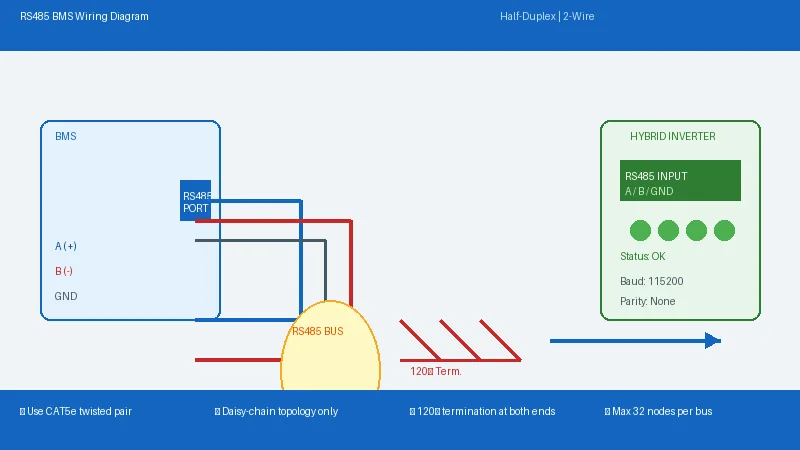
RS485 is a half-duplex differential signaling standard. It uses two wires (A and B) to transmit data over long distances — up to 1,200 meters — making it ideal for multi-stack battery installations spread across a building or property. RS485 requires only two wires, which simplifies wiring in retrofits and reduces material costs.
In a typical LiFePO4 setup, the BMS exposes an RS485 port that connects directly to the inverter’s RS485 input. The inverter polls the battery for SOC, voltage, current, temperature, and alarm status at regular intervals.
Key Specifications
- Max distance: 1,200 meters (without repeaters)
- Max speed: 10 Mbps (but typically 9,600–115,200 baud for BMS use)
- Topology: Bus (daisy-chain), no star topology
- Devices per bus: Up to 32 devices (transceivers)
- Protocol layer: Physical only — requires higher-layer protocol (e.g., Modbus RTU) for data framing
Common BMS Brands Using RS485
DALY BMS and JBD (Jiabaida) most commonly use RS485 as their primary inverter communication port. Seplos BMS also supports RS485 alongside CAN. RS485 is the default choice for budget and mid-tier battery integrations where long cable runs are anticipated.
Pros and Cons of RS485
| Advantages | Disadvantages |
|---|---|
| Long cable runs (up to 1.2 km) | Only half-duplex (cannot send and receive simultaneously) |
| Simple 2-wire wiring | No native error detection — depends on application layer |
| Widely supported by inverters | No standardized data format — each BMS brand uses proprietary frames |
| Inexpensive transceivers | Slow data refresh rates compared to CAN |
CAN Bus: The Automotive-Grade Standard
How CAN Bus Works
Controller Area Network (CAN Bus) was developed by Bosch for automotive applications in the 1980s and has since been adopted by EV manufacturers and industrial energy storage systems worldwide. Unlike RS485’s physical-layer-only approach, CAN Bus defines a full data link layer with built-in error detection, message prioritization, and collision avoidance.
In a LiFePO4 context, CAN Bus enables high-speed, reliable communication between the battery BMS and the inverter or energy management system (EMS). Data refresh rates of 125 kbps to 1 Mbps are standard, allowing the inverter to react to battery state changes in milliseconds.
Key Specifications
- Max distance: 40 meters at 1 Mbps (longer at lower speeds)
- Max speed: 1 Mbps
- Topology: Bus (daisy-chain or stub connections)
- Devices per bus: Up to 120 nodes
- Error detection: CRC, ACK slots, bit stuffing — very robust
CAN Bus in Commercial and High-Performance Home Systems
High-capacity systems using 314Ah and 320Ah prismatic LiFePO4 cells frequently rely on CAN Bus for inverter communication. Brands like Pylontech, BYD, and some Seplos configurations default to CAN. Commercial telecom battery installations — as explored in our telecom base station battery guide — almost exclusively use CAN Bus due to its reliability in noisy electrical environments.
Pros and Cons of CAN Bus
| Advantages | Disadvantages |
|---|---|
| Built-in error detection and correction | Shorter maximum cable distance than RS485 |
| High-speed data (up to 1 Mbps) | Requires twisted-pair shielded cable for best results |
| Message prioritization prevents data collisions | More expensive transceivers than RS485 |
| Works in electrically noisy environments | Requires proper termination resistors (120Ω at both ends) |
Modbus RTU and Modbus TCP: The Industrial Standard
Modbus RTU vs Modbus TCP
Modbus is the oldest industrial protocol in common use — developed by Modicon in 1979 — but it remains one of the most widely supported communication standards in energy storage systems. It comes in two flavors relevant to BMS communication:
- Modbus RTU: Runs over RS485 physical layer. Combines the long-distance capability of RS485 with the structured data format of Modbus.
- Modbus TCP: Runs over Ethernet (TCP/IP). Used when the BMS or inverter has an Ethernet port and the system is on a local network.
Modbus organizes data into holding registers — numbered memory locations that the master (inverter/EMS) reads or writes to query battery parameters. This standardized register map makes Modbus particularly attractive for system integrators working with multiple BMS brands, as the data format is predictable.
Modbus in Hybrid Inverter Systems
Many hybrid inverters from brands like Victron Energy, Solis, and SMA support Modbus RTU or Modbus TCP for battery integration. If your BMS supports Modbus, you get a plug-and-play experience without needing to reverse-engineer proprietary communication frames. This is especially valuable in off-grid and hybrid inverter configurations where the inverter needs to manage charging, discharging, and grid export based on real-time battery data.
Pros and Cons of Modbus
| Advantages | Disadvantages |
|---|---|
| Standardized register map — works across brands | Slower than CAN Bus (especially Modbus RTU at 9,600 baud) |
| Supports both serial (RTU) and Ethernet (TCP) | Master-slave architecture — BMS cannot initiate messages |
| Well-documented and widely understood | No native security (unencrypted communication) |
| Easy integration with SCADA and home automation | Register addressing varies between manufacturers |
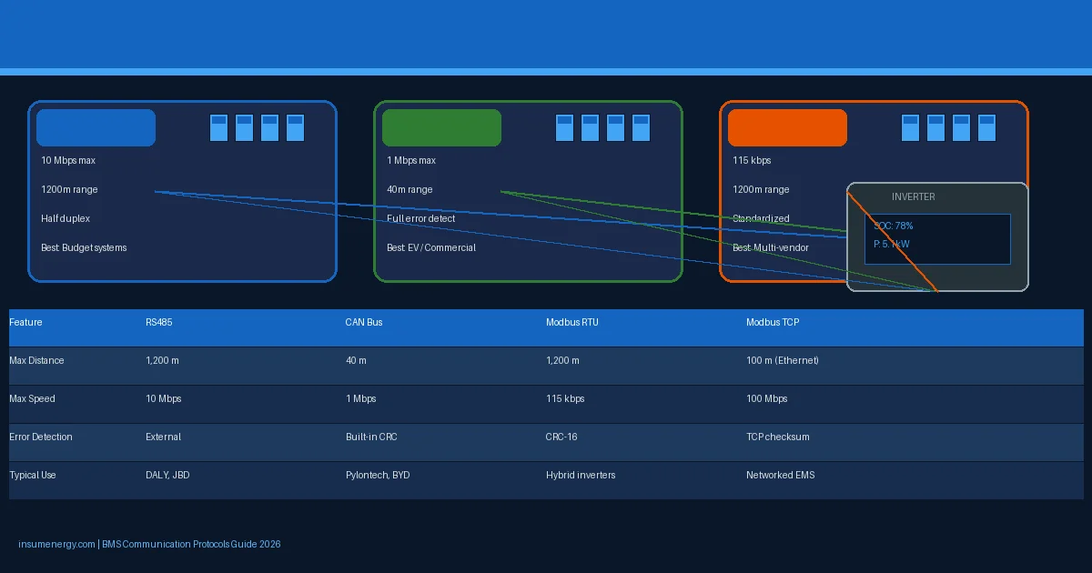
Side-by-Side Protocol Comparison
| Feature | RS485 | CAN Bus | Modbus RTU | Modbus TCP |
|---|---|---|---|---|
| Max Distance | 1,200 m | 40 m (1 Mbps) | 1,200 m (RS485) | 100 m (Ethernet) |
| Max Speed | 10 Mbps | 1 Mbps | 115.2 kbps | 100 Mbps |
| Duplex | Half | Half | Half | Full |
| Error Detection | External | Built-in (CRC) | CRC-16 | TCP/IP checksum |
| Typical BMS Brands | DALY, JBD, Seplos | Pylontech, BYD, Seplos | Various (via RS485) | High-end inverters |
| Cost | Low | Medium | Low | Medium |
| Best For | Long runs, budget systems | EV/commercial, high speed | Multi-vendor integration | Networked systems |
How to Choose the Right Protocol for Your System
Protocol selection isn’t arbitrary — it depends on your inverter’s capabilities, the BMS brand, cable run distances, and the level of data detail you need. Here’s a practical decision framework:
Choose RS485 if:
- Your inverter only supports RS485 (many budget inverters do)
- You have long cable runs between battery and inverter (over 40 meters)
- You’re using DALY, JBD, or lower-tier BMS hardware
- Cost is a primary concern
Choose CAN Bus if:
- Your inverter and BMS both support CAN natively
- You need real-time, high-speed data (sub-second SOC updates, alarm propagation)
- You’re installing in an electrically noisy commercial or industrial environment
- You want accurate state of health (SoH) tracking with minimal latency
Choose Modbus if:
- You need to integrate multiple devices (battery, inverter, solar PV, EV charger) on one network
- You’re building a SCADA or home automation system around your battery
- Your inverter is a Victron, SMA, or Solis hybrid unit
- You want a vendor-agnostic approach that doesn’t lock you into one BMS brand
Wiring Tips and Common Mistakes to Avoid
RS485 Wiring Checklist
- Use twisted-pair cable (CAT5e or better) for A and B signals
- Do not use star topology — all devices must be daisy-chained on the same bus
- Terminate the bus with 120Ω resistors at both ends if cable runs exceed 10 meters
- Keep signal cables at least 20 cm away from AC power cables
- Check BMS brand documentation for the correct baud rate (9,600 or 115,200 are common)
CAN Bus Wiring Checklist
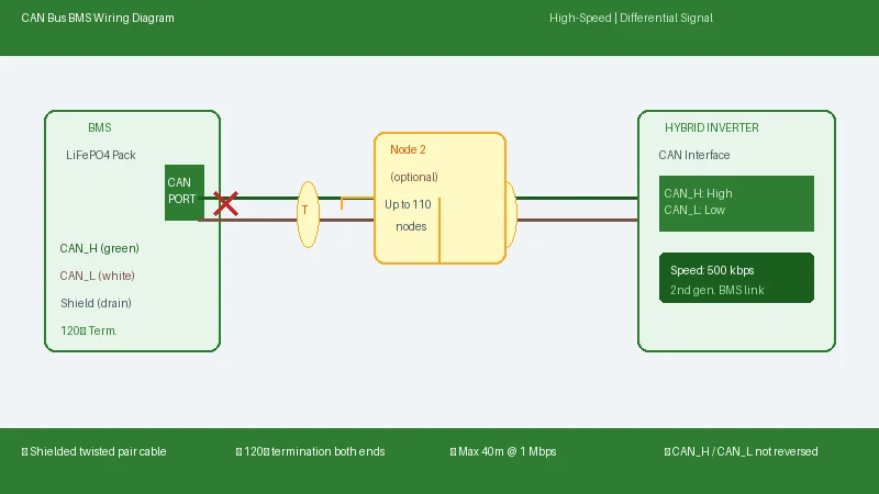
- Always use shielded twisted-pair CAN cable (2×0.5mm² minimum)
- Install 120Ω termination resistors at both bus ends — never in the middle
- Keep CAN bus under 40 meters for 1 Mbps operation; up to 500 meters at 50 kbps
- Do not splice CAN cables — continuous runs are more reliable
- Verify CAN_H and CAN_L are not reversed (reversed polarity kills communication silently)
Modbus TCP Checklist
- Use a dedicated Ethernet switch — do not share with high-traffic network segments
- Assign static IP addresses to avoid DHCP conflicts
- Verify the Modbus register map matches between BMS and inverter (common source of integration failure)
- Check firewall rules if accessing battery data remotely
Multi-Stack Communication: Connecting Multiple Battery Packs
When you need more capacity than a single battery can provide, you’ll connect multiple packs in parallel. This is where communication protocols become critical — and where most installation errors occur.
In a multi-stack battery parallel system, one battery is designated as the master and others as slaves. The master BMS communicates with the inverter on behalf of the entire bank, aggregating SOC, voltage, current, and temperature data from all connected packs. The master-slave chain is typically connected via RS485 or CAN.
The most common pitfall is circulating current between paralleled packs — a phenomenon where one battery tries to charge another through the parallel bus, causing uneven wear and premature degradation. Proper BMS communication ensures the master BMS actively balances charge distribution across all stacks, preventing this issue. High-quality systems with active balancing BMS solutions detect and correct circulating current automatically.
Future Trends: What’s Next for BMS Communication
The energy storage industry is evolving rapidly. Several trends are reshaping how BMS devices communicate:
- CAN FD (Flexible Data Rate): An upgraded CAN standard that supports up to 8 Mbps — increasingly common in next-generation battery packs with high-speed data logging requirements.
- Wireless BMS (wBMS): Eliminating physical wiring between cells within a battery pack — reducing weight and complexity, particularly relevant for marine and RV applications.
- Modbus TCP/IP over Ethernet: As more inverters gain network connectivity, Modbus TCP is replacing serial Modbus RTU in new residential installations.
- SunSpec Alliance standards: A growing industry consortium working to standardize battery-inverter communication using a common data model — reducing the configuration headaches that plague current installations.
Conclusion: Match Your Protocol to Your System
BMS communication protocols are the invisible backbone of every reliable LiFePO4 energy storage system. RS485, CAN Bus, and Modbus each serve different needs — there’s no single “best” protocol, only the right choice for your specific hardware combination and installation environment.
If you’re planning a new installation, the most important step is to verify protocol compatibility between your BMS and inverter before purchasing. A 30-minute compatibility check now can save days of troubleshooting later. For multi-stack systems or commercial installations, working with a certified installer ensures proper termination, address configuration, and data validation.
At Insum Energy, we supply complete LiFePO4 battery systems with matched BMS-inverter communication configurations. Our technical team can recommend the optimal protocol setup for your residential, commercial, or off-grid project — and handle the integration for you.
Ready to build a reliable battery system? Contact Insum Energy today for a customized quote and system design consultation.



2 Comments