DIY LiFePO4 Battery Pack Assembly Guide: Complete Step-by-Step Instructions
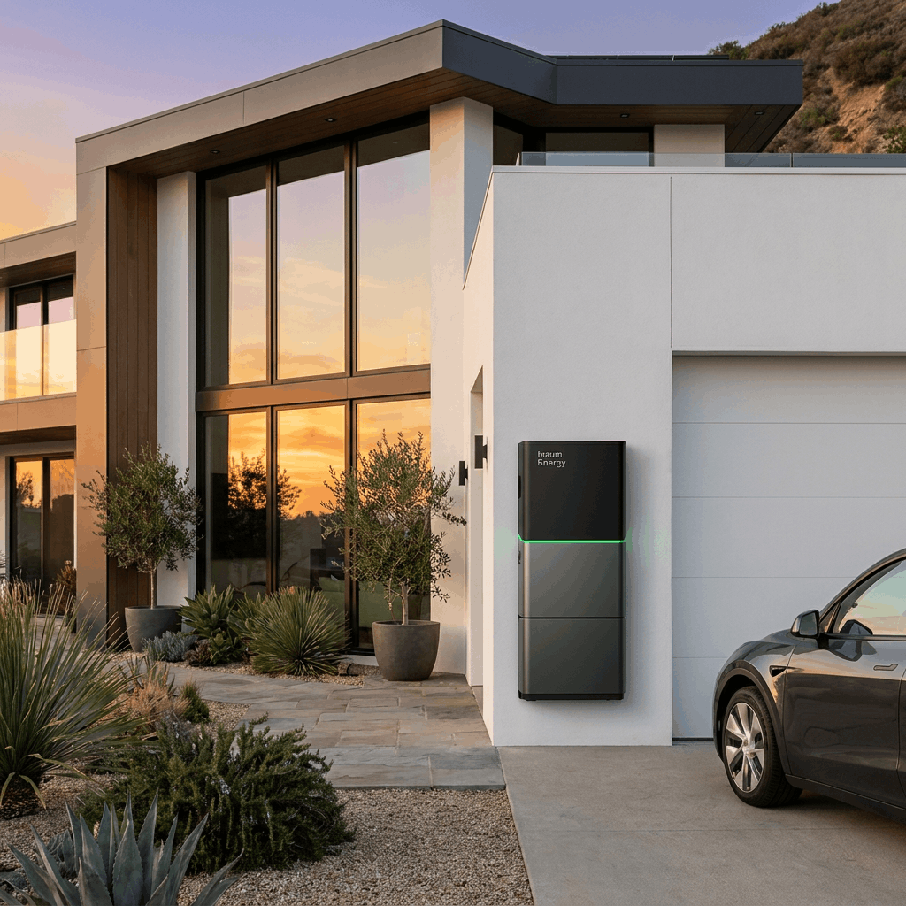
Building your own LiFePO4 battery pack is one of the most rewarding ways to invest in home energy storage. Whether you’re designing a system for a solar installation, an off-grid cabin, or a backup power solution, assembling a battery pack from quality Grade A cells gives you full control over capacity, voltage, and scalability — all at a significantly lower cost than pre-built units.
This guide walks you through every step of the process, from cell selection and testing to final commissioning. Follow these steps carefully and your DIY LiFePO4 battery will deliver reliable performance for 10+ years.

What You Need Before You Start
Preparation is the most critical phase. Rushing into assembly without proper tools and verified components is the leading cause of failure and safety incidents. Here’s your complete checklist.
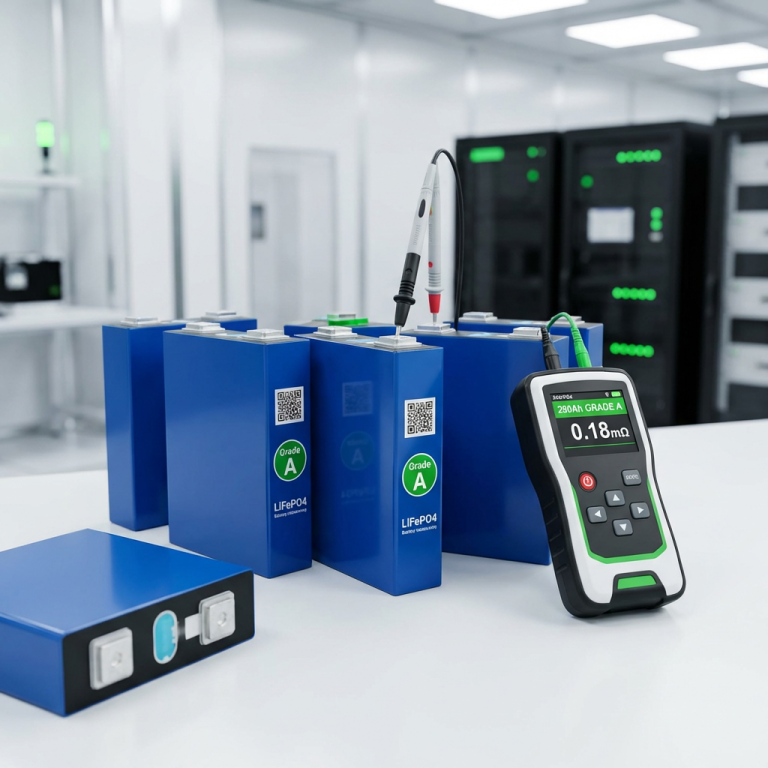
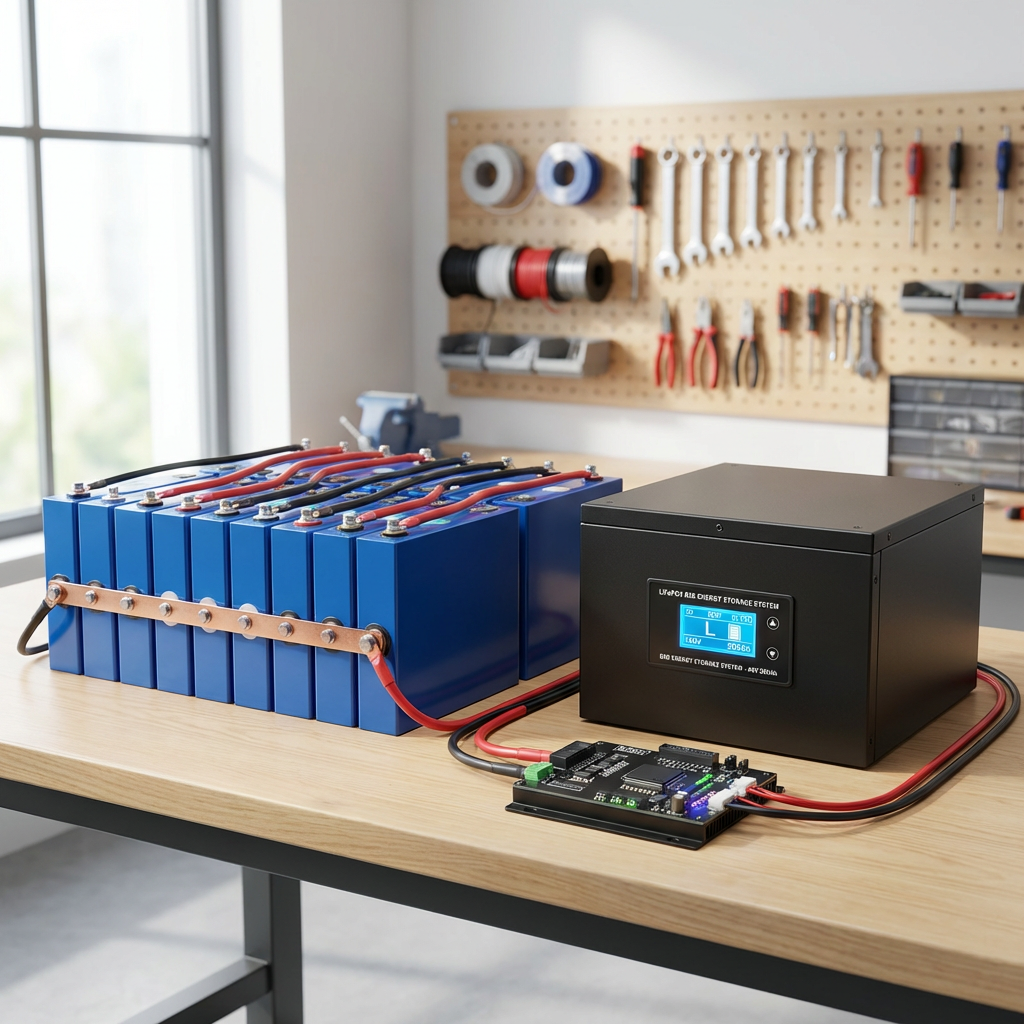
- LiFePO4 cells — Grade A prismatic cells (280Ah, 304Ah, or 314Ah are most popular for home storage)
- BMS (Battery Management System) — matched to your cell configuration (16S for 48V, 4S for 12V)
- Nickel strips — typically 0.15mm × 8mm pure nickel for series connections
- Copper busbars — for parallel connections between cell groups
- Spot welder — pulsed spot welder with ≥2,000A peak current (mandatory — never solder LiFePO4 cells)
- Insulation materials — Kapton tape, fish paper, and PET insulation sheets
- Torque wrench — 3–10 Nm range for terminal bolts
- Cell balancer / tester — for voltage verification before and after assembly
- PPE — safety glasses, insulated gloves, and a Class D fire extinguisher
Step 1: Verify and Test Every Cell Before Assembly
Never skip cell verification. Even cells from the same batch can have subtle voltage and internal resistance differences that affect pack longevity. Use a LiFePO4 cell tester or a precision voltmeter to record each cell’s:
- Open-circuit voltage (OCV) — should be within 3.20–3.35V for a resting cell at approximately 50% SoC
- Internal resistance (IR) — measured in mΩ; cells within 0.2mΩ of each other group best
- Physical condition — no dents, swelling, or damaged terminals
Sort cells into groups with matched voltage (±0.05V) and internal resistance (±0.1mΩ). This balancing step dramatically improves pack uniformity and extends overall cycle life. Insum Energy supplies pre-tested Grade A cells with OCV and IR test reports included.

Step 2: Plan Your Busbar Configuration
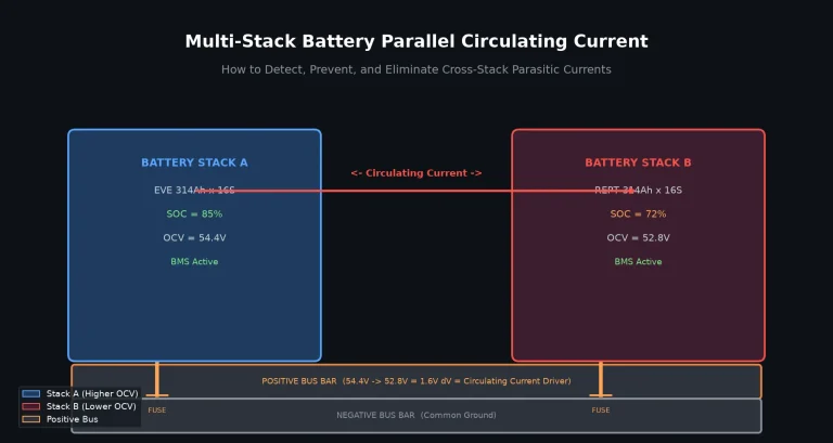
For a 48V system (16S configuration), you’ll arrange 16 cells in series. Each series string is a “group.” If you’re building a large capacity system (e.g., 100Ah+), you’ll parallel multiple 16S groups to reach your target amp-hour capacity.
Nickel strip sizing rule: Allow approximately 3mm² of cross-sectional nickel area per ampere of continuous discharge current. For a 100A continuous discharge system, use ≥8mm wide × 0.15mm thick pure nickel strips. For higher currents, consider copper-nickel composite (copper core with nickel plating) to reduce resistance.
Step 3: Spot Weld the Cell Connections
Spot welding is the only approved method for joining LiFePO4 cells. Soldering generates excessive heat that degrades the cell’s internal chemistry and can cause thermal runaway.
- Set your spot welder to 2.5–3.5ms pulse width, 300–400V capacitor voltage
- Make 2–3 spot welds per tab connection point for 0.15mm nickel strips
- For 0.20mm thick strips, increase to 3–4 welds per point
- Always weld on a fire-resistant surface and keep a Class D fire extinguisher nearby
- Double-check polarity — a reversed series connection can cause an immediate short-circuit
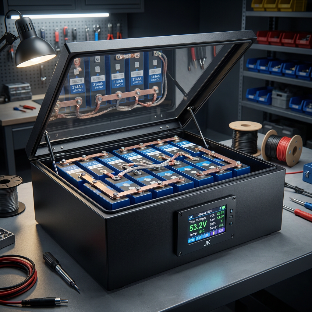
Step 4: Install and Configure the BMS
The BMS is the brain of your battery pack. It monitors individual cell voltages, controls charging balance, and protects against over-current, over-temperature, and short circuits. For 48V systems, use a 16S BMS rated for at least 100A continuous discharge current.
- Connect the sense cable — each of the 16 balance connector wires goes to the corresponding series connection point
- Install the current shunt — on the negative terminal of the battery pack
- Configure over/under-voltage thresholds — typically 3.65V/cell (charge cut-off) and 2.8V/cell (discharge cut-off)
- Set the temperature limit — 60°C maximum for charge, 65°C for discharge
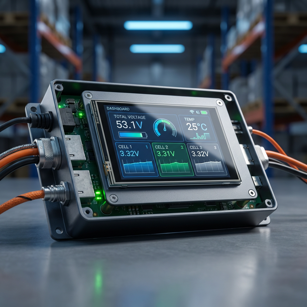
- Enable Bluetooth or RS485 — for real-time monitoring via smartphone app or inverter integration
Step 5: Insulate, Enclose, and Torque
Proper insulation prevents short circuits between cells and the enclosure. Apply Kapton tape to all exposed busbar joints, and use PET insulation sheets between parallel cell groups. When mounting the completed pack in an enclosure:
- Use M6 or M8 stainless steel terminal bolts with lock washers
- Torque to 3–5 Nm for M6 bolts, 6–8 Nm for M8 bolts — never over-torque, which can crack the cell terminal seal
- Apply silicone dielectric grease to terminal connections to prevent oxidation
- Ensure the enclosure has adequate ventilation (minimum 10mm gap on all sides)
- Ground the enclosure to your system’s protective earth
Step 6: Commissioning and First Charge
Before connecting your pack to a solar inverter or home grid system, perform a controlled first charge:
- Charge at ≤0.2C (20A for a 100Ah pack) for the first 3 cycles to form the electrode interface
- Monitor cell voltages throughout — no single cell should exceed 3.65V
- Verify BMS balance function activates during charging
- Check enclosure temperature — it should not exceed 40°C during the first full charge
- Record baseline data: total pack voltage, individual cell voltages, and BMS parameters
Essential Safety Checklist
- ✅ Work on a non-conductive surface (wooden bench or rubber mat)
- ✅ Wear safety glasses and insulated gloves throughout assembly
- ✅ Have a Class D fire extinguisher within reach
- ✅ Never leave a pack unattended while charging
- ✅ Label the pack with voltage, capacity, and assembly date
- ✅ Store unused cells at 40–60% SoC for long-term shelf life
Conclusion
Building a DIY LiFePO4 battery pack is a skilled but achievable project for anyone comfortable with basic electrical work. The key to success lies in quality components, meticulous cell matching, proper spot welding technique, and a well-configured BMS. When done right, a DIY 48V 100Ah LiFePO4 pack can cost 30–50% less than a commercial equivalent — while delivering 6,000+ cycles at 80% depth of discharge.
If you’d like a custom battery solution engineered and built to your exact specifications, contact Insum Energy. We specialize in bespoke LiFePO4 energy storage systems for homes, businesses, and off-grid installations across Europe, with CE and UN38.3 certified products and fast delivery from our Poland warehouse.
Ready to start your project? Browse our range of Grade A LiFePO4 cells, BMS modules, and complete DIY kits — or reach out to learn how we can build your battery system for you.