
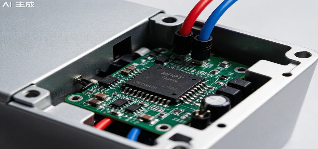
MPPT Algorithm Explained: How Solar Inverters Maximize Power Output
Every solar panel has a sweet spot—a specific operating voltage and current where it produces the most power. For a 400W panel under standard test conditions, that sweet spot sits around 41V and 9.75A. But the moment clouds pass overhead, temperature shifts, or panels age, that optimal operating point drifts. Without a mechanism to track and follow it, your system runs below its potential. That mechanism is the MPPT algorithm—the brain inside every modern solar inverter.
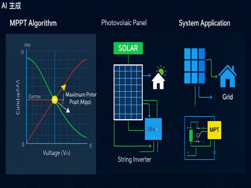
What Is MPPT and Why Does It Matter?
MPPT stands for Maximum Power Point Tracking. It is a digital control algorithm embedded in solar inverters and charge controllers that continuously adjusts the electrical load presented to your photovoltaic (PV) panels. The goal: operate the panels at their maximum power point (MPP) at all times, under all conditions.
To understand why this matters, you need to understand the PV curve—the relationship between a solar panel’s voltage and current output.
At open circuit (zero current), voltage peaks at Voc. At short circuit (zero voltage), current peaks at Isc. Between these extremes lies a curve where power output reaches a single maximum point. This is the MPP. A panel’s datasheet specifies this point as Vmp (voltage at maximum power) and Imp (current at maximum power).
Without MPPT, a direct-coupled system—where the panel connects straight to a battery or load without an inverter stage—might operate at the battery’s voltage (~48V for a 4-cell LiFePO4 pack), far from the panel’s Vmp of 40V+. The power loss from this mismatch alone can reach 20–30% of your system’s potential output. MPPT inverters close that gap.
How the PV Power Curve Works
The power curve of a PV panel is not a straight line. It has a single peak under uniform irradiance—a hill with the MPP at its summit. Here’s what shifts that peak:
- Irradiance change (cloud cover, sun angle): shifts the MPP current, moving the peak up or down the curve
- Temperature change: higher cell temperature reduces Voc and shifts the MPP to a lower voltage—LiFePO4 cells in hot climates see ~0.4%/°C voltage reduction
- Aging and degradation: panels lose output over 25 years, slowly shifting the entire curve
An effective MPPT algorithm must sense these changes and reposition the operating point in real time.
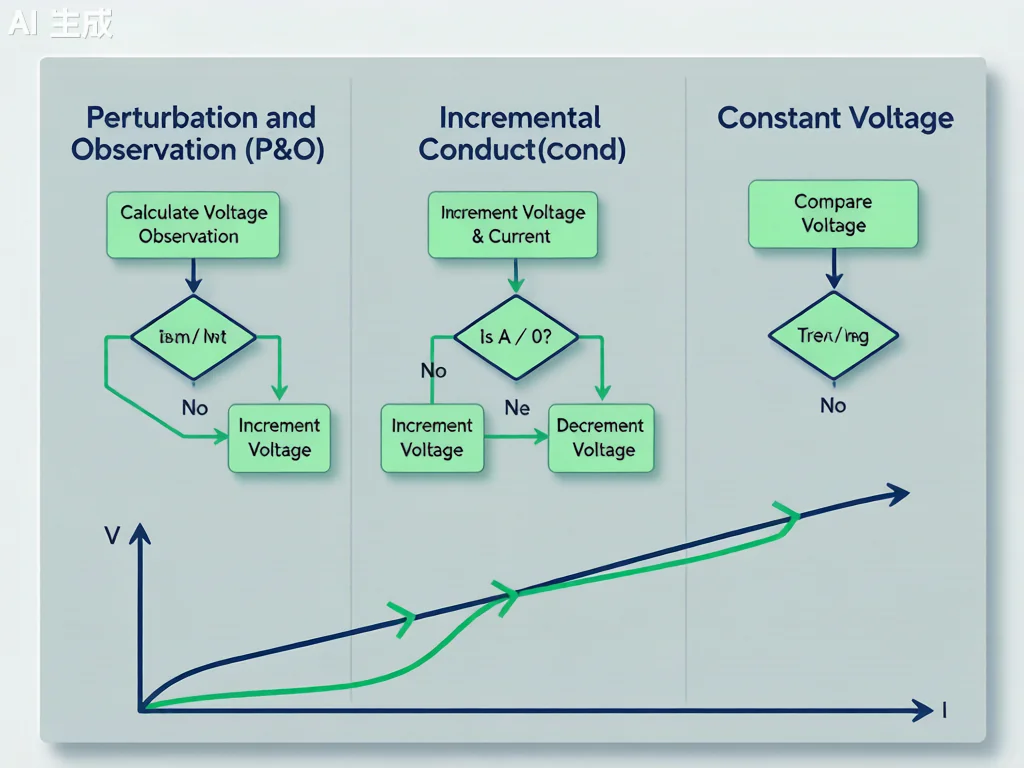
The 4 Main MPPT Algorithms Explained
1. Perturbation and Observation (P&O)
Perturbation and Observation is the most widely used MPPT algorithm in residential and commercial inverters. Its logic is elegantly simple:
- Measure the panel’s current voltage (V) and current (I)
- Calculate power (P = V × I)
- Perturb (slightly adjust) the operating voltage
- Compare the new power to the previous reading
- If power increased → continue perturbing in the same direction
- If power decreased → reverse the perturbation direction
The algorithm “hill climbs” toward the MPP by taking small steps. Its main drawbacks are oscillation around the MPP (it never settles perfectly) and slow tracking speed under rapidly changing irradiance. Most budget inverters use P&O, accepting ~2–5% power loss from oscillation as a tradeoff for simplicity.
2. Incremental Conductance (IncCond)
Incremental Conductance is a more mathematically precise algorithm based on the derivative of panel power with respect to voltage:
- At the MPP: dP/dV = 0
- Left of MPP: dP/dV > 0 (power increasing with voltage)
- Right of MPP: dP/dV < 0 (power decreasing with voltage)
By comparing instantaneous conductance (I/V) against incremental conductance (ΔI/ΔV), the algorithm can determine its position relative to the MPP in a single step. IncCond tracks faster than P&O under changing conditions and produces less oscillation. It is the preferred algorithm in premium hybrid inverters and string inverters where efficiency matters.
3. Constant Voltage (CV)
The Constant Voltage algorithm simplifies MPPT to a single rule: maintain the panel voltage at a fixed ratio of Voc (typically 0.76–0.80). The relationship Vmp ≈ 0.76 × Voc holds reasonably well across temperature ranges for crystalline silicon panels.
The advantage is extreme simplicity—no continuous power calculation is needed. The tradeoff is accuracy: under partial shading or non-standard conditions, the 0.76 ratio no longer reflects the true MPP, and power loss can reach 10–15%. Constant Voltage is commonly used as a fallback mode or in basic PWM charge controllers where cost is the primary constraint.
4. Fractional Open-Circuit Voltage (FOCV)
Fractional Open-Circuit Voltage periodically disconnects the panel from the inverter to measure the true Voc, then sets Vmp to a fixed fraction of that reading. This is essentially a refined version of the Constant Voltage method, but with regular recalibration.
The short disconnection (typically 1–5ms) causes a negligible power loss, but provides updated reference data. FOCV works well in stable climates but struggles in locations with frequent cloud cover.
Partial Shading: The Hardest MPPT Challenge
Under uniform sunlight, a PV array has a single clean peak on its power curve. But when panels are partially shaded—by trees, chimneys, or neighboring panels—the IV curve develops multiple local peaks, not just one global maximum.
Standard P&O and IncCond algorithms can get trapped on a local peak, never finding the true global maximum. This is one of the most significant sources of energy loss in rooftop solar systems.
Solutions for Partial Shading
- Distributed MPPT (DMPPT): Each panel or small string gets its own MPPT channel. This eliminates shading interaction between panels entirely—used in microinverters and some premium string inverters with multiple MPPTs
- Global Maximum Power Point Tracking (GMPPT): Enhanced algorithms that periodically sweep the entire IV curve to locate all peaks, then jump to the global maximum. More computationally intensive but effective
- Module-Level Power Electronics (MLPE): Microinverters and DC optimizers that perform MPPT at each panel individually
MPPT Specifications: What to Look For in an Inverter
Not all MPPT implementations are equal. When evaluating a solar inverter or hybrid system, check these specifications:
| Specification | Why It Matters | Recommended Range |
|---|---|---|
| Number of MPPT channels | Multiple MPPTs allow independent optimization of different panel orientations or string configurations | 2–4 for residential; more for complex arrays |
| MPPT voltage window | The inverter must operate within the panel’s Vmp range across all temperatures | 100V–500V typical for home systems |
| Tracking speed | Faster algorithms respond better to cloud transients | <1 second full sweep preferred |
| Operating voltage range | Wider range = more flexibility in system design and panel count | Check compatibility with your specific panel’s Vmp |
| Efficiency at partial load | Most real-world operation occurs below full rated power | >98% weighted efficiency |
How Many Panels Per String? MPPT String Sizing
Getting string sizing right is essential for MPPT performance. String too short and the inverter can’t reach its minimum input voltage. String too long and the panel voltage exceeds the inverter’s maximum, triggering clipping losses.
The key calculation involves your panel’s Vmp at the lowest expected temperature (cold = higher voltage) and Vmp at the highest temperature (hot = lower voltage). The MPPT window must accommodate both extremes. Most quality inverters offer online string calculators to simplify this process.
For a typical 400W monocrystalline panel with Vmp of 40V:
- Minimum string length: inverter MPPT min voltage ÷ panel Vmp (accounting for temperature)
- Maximum string length: inverter MPPT max voltage ÷ panel Vmp at coldest expected temp
MPPT and LiFePO4 Battery Storage Systems
In home energy storage systems, the MPPT algorithm must coordinate between two objectives: maximizing solar harvest and managing battery charging. This is where hybrid inverters with built-in MPPT controllers excel.
A quality hybrid inverter with multi-channel MPPT can:
- Connect east-facing and west-facing panel arrays to separate MPPT channels for independent optimization
- Prioritize self-consumption by directing excess solar to battery charging when generation exceeds household demand
- Transition seamlessly between grid-tie, off-grid, and backup modes while maintaining MPPT operation
- Work with high-voltage LiFePO4 battery packs (48V–400V) commonly used in residential storage
For installers designing systems with Insum Energy’s residential and commercial storage solutions, selecting an inverter with ≥2 MPPT channels and a wide operating window (200V–550V) provides maximum flexibility across different roof configurations and future expansion.
Conclusion: MPPT Is the Intelligence Behind Every Efficient Solar System
The MPPT algorithm is not a luxury feature—it is the fundamental reason modern solar systems achieve 98%+ conversion efficiency rather than the 70–80% achievable with simple direct-coupling. Whether you choose Perturbation and Observation for its proven reliability or Incremental Conductance for its precision, the underlying principle remains the same: continuously hunt for and hold the panel’s maximum power point.
For homeowners and installers planning residential energy storage, the quality of the MPPT implementation matters as much as panel efficiency. Multiple MPPT channels, wide voltage windows, and fast-tracking algorithms justify the investment in premium hybrid inverters—delivering measurable energy yield gains year after year.
Ready to design an optimally configured solar + storage system? Contact Insum Energy for a professional system assessment and tailored quotation for your home or business.