Multi-Stack Battery Parallel Circulating Current: How to Avoid It in 2026
Expanding a home energy storage system beyond a single battery pack means connecting multiple stacks in parallel. It sounds straightforward — just tie the positive and negative bus bars together. But the moment you do, a hidden threat appears: parallel circulating current.
This parasitic current flows continuously between stacks, draining energy, heating components, and slowly degrading your entire system — often without any alarm until damage is already done. This guide explains exactly what it is, why it happens, how to detect it, and most importantly, how to prevent it.
What Is Parallel Circulating Current?
When two or more battery stacks are connected in parallel, current doesn’t just flow to your load. It also flows internally between the stacks themselves, driven by any difference in open-circuit voltage (OCV) between them.
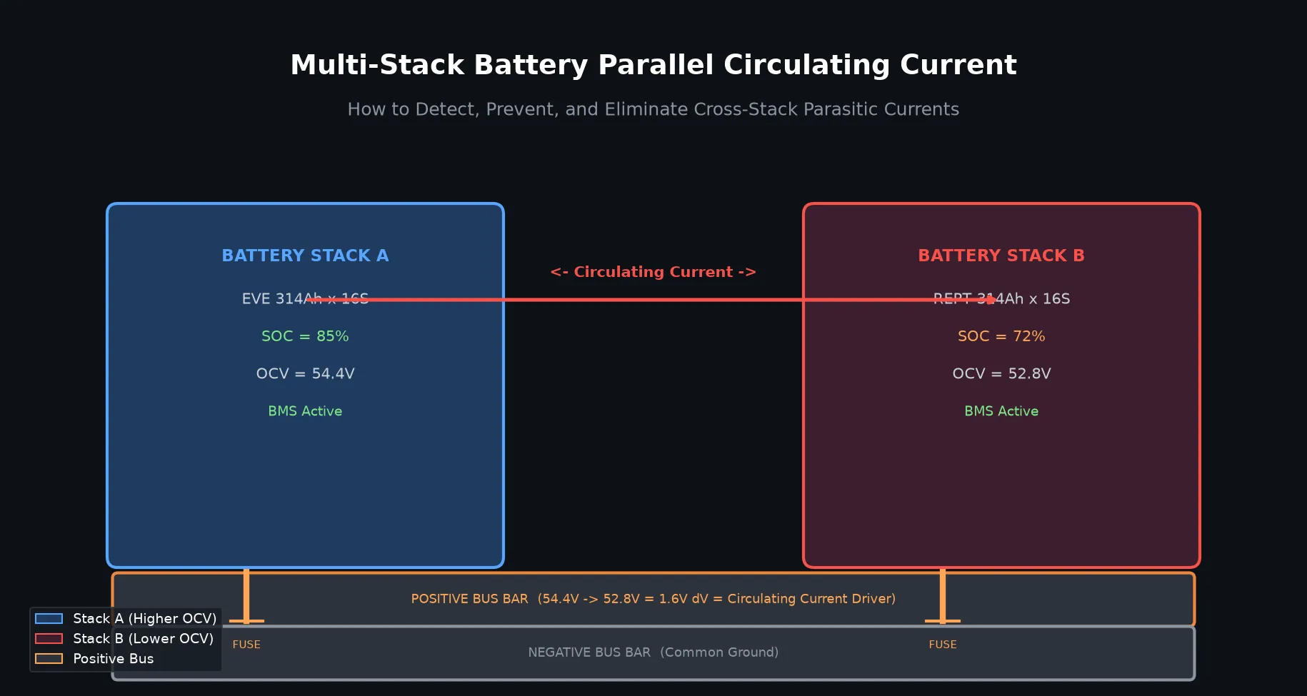
Here’s the simplified mechanism:
- Stack A has a higher OCV (e.g., 54.4V at 85% SOC)
- Stack B has a lower OCV (e.g., 52.8V at 72% SOC)
- The 1.6V difference drives electrons from Stack A through the bus bar into Stack B — even when no load is connected
- Stack A over-discharges slightly; Stack B over-charges slightly
- The BMS on each stack may interpret this as an anomaly and shut down
The Physics Behind It
The circulating current can be calculated using Ohm’s Law:
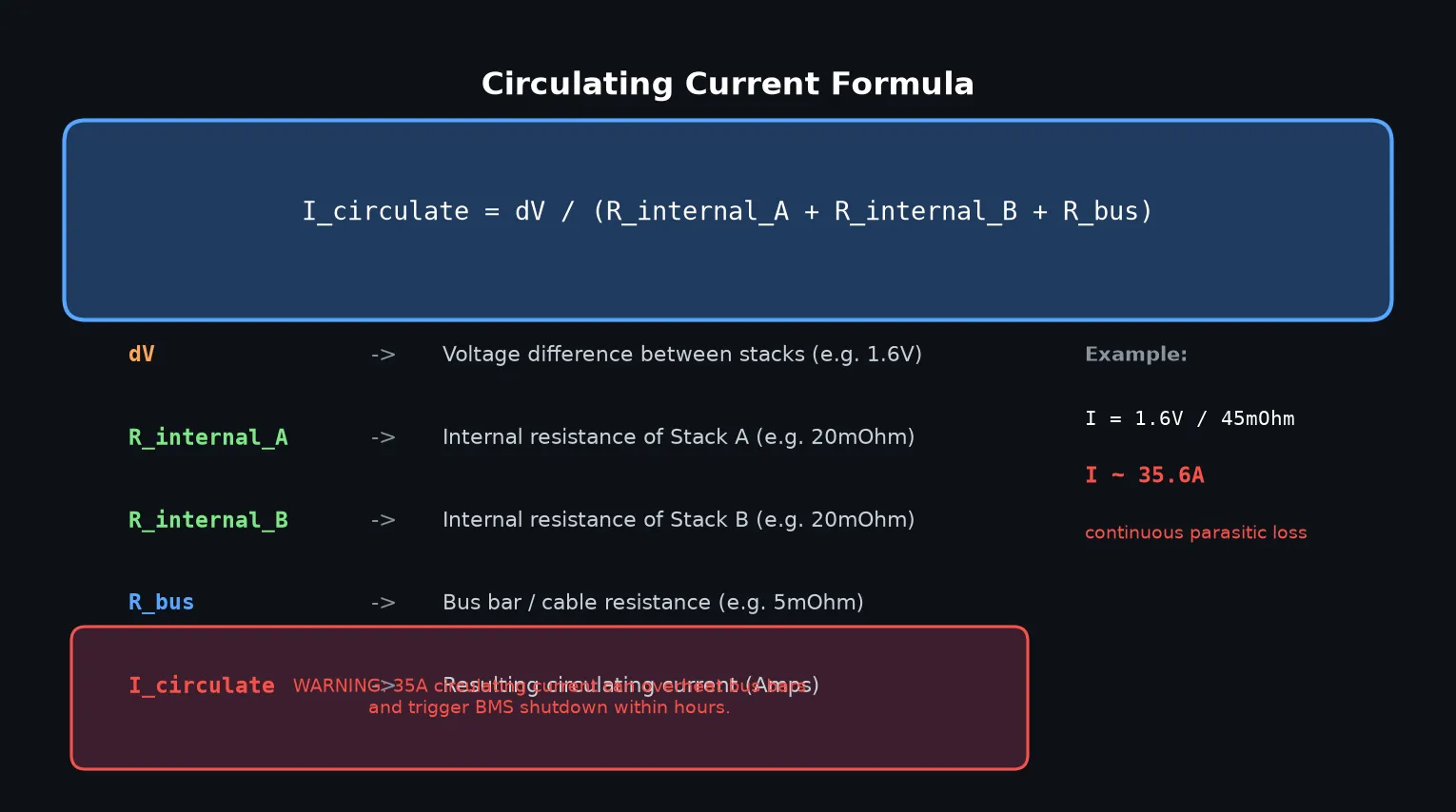
For a typical two-stack 48V system:
- dV of 1.6V between stacks
- 20mΩ internal resistance per stack
- 5mΩ bus/cable resistance
- Result: ~35A of continuous circulating current
35A doesn’t sound catastrophic — but it operates 24/7 without interruption, converts to heat, and shortens BMS relay life significantly.
Why This Matters for Home Energy Storage
Residential installations typically use 2–4 battery stacks in parallel. Even a small 0.5V OCV mismatch between stacks (common with different brands or ages of cells) creates measurable circulating current.
The consequences accumulate over months:
- Energy loss: Circulating current generates continuous I²R heat losses — no useful work is done
- BMS interference: Both BMS units may detect cross-current and trigger protection mode independently
- Accelerated wear: The higher-SOC stack discharges faster than designed; the lower-SOC stack receives excess charge
- System instability: Combined BMS behaviors can cause frequent connect/disconnect cycles, wearing out contactors
- Safety risk: Uncontrolled current during fault conditions can exceed cable ampacity ratings
5 Proven Methods to Prevent Circulating Current
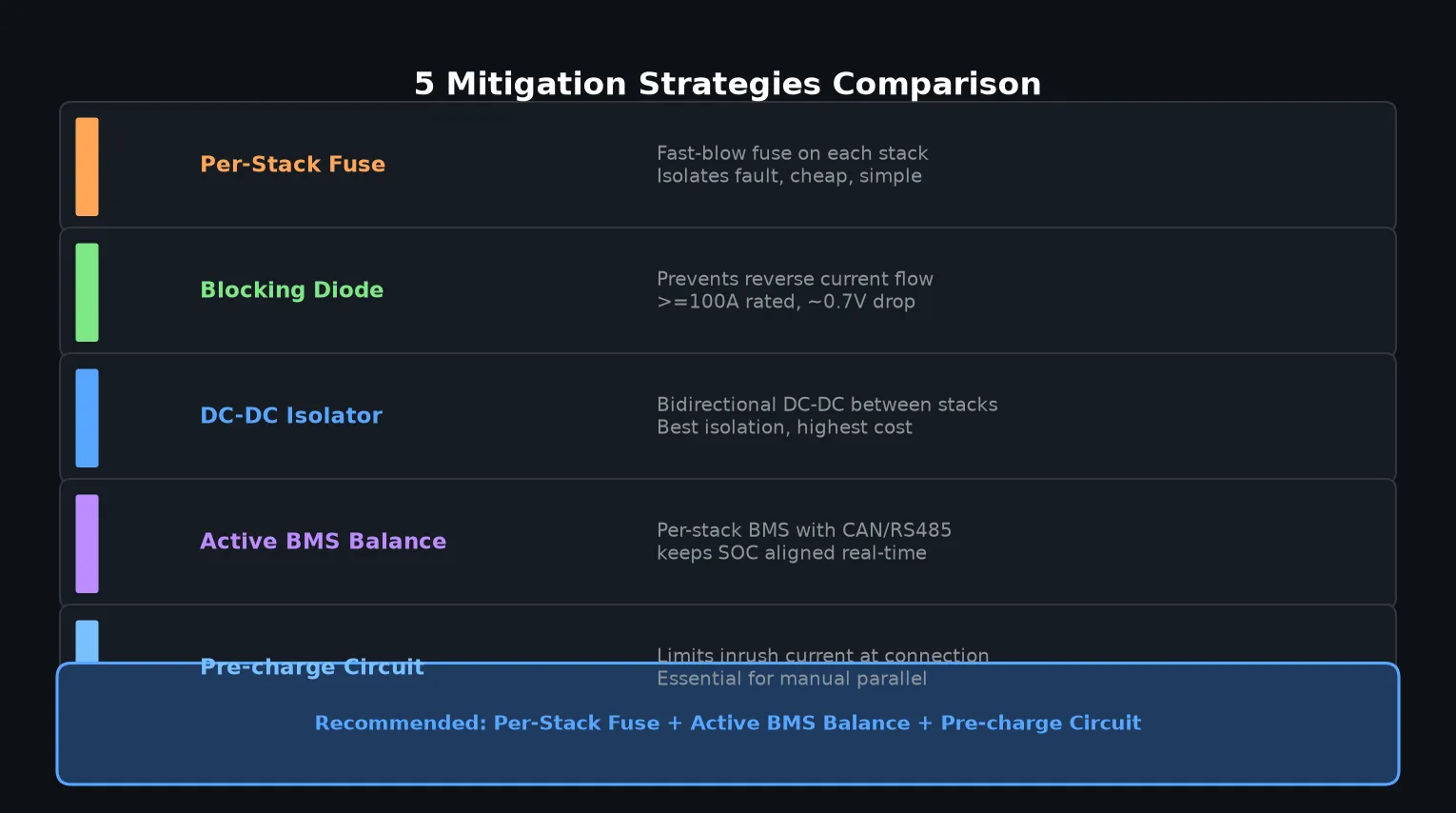
Method 1: Per-Stack Fast-Blow Fuses
The most fundamental and cost-effective protection. Install a Class T or ANL fuse (rated ≥100A for 48V systems) on the positive terminal of each stack before it connects to the common bus.
Pros: Inexpensive (~$15–30 per fuse), simple to install, provides fault isolation
Cons: Must be manually reset/replaced after a fault
Method 2: Blocking Diodes
A high-current Schottky or silicon diode installed in series with each stack’s positive output prevents reverse current flow.
Pros: Completely blocks reverse current, passive (no configuration needed)
Cons: ~0.7V voltage drop across the diode reduces usable system voltage; generates heat at high current
Method 3: DC-DC Isolator (Best Isolation)
Place a bidirectional DC-DC converter between the stacks. Each stack operates at its own optimal voltage, and the converter manages power flow intelligently.
Pros: Complete electrical isolation, active power management, no circulating current possible
Cons: Expensive ($400–$1,200+), efficiency loss (~3–5%), complex installation
Method 4: Active BMS Balancing
Use BMS units with CAN or RS485 communication to actively synchronize state of charge across stacks in real time. When both stacks share the same SOC, their OCVs converge, minimizing the driving force for circulating current.
At Insum Energy, we recommend JK BMS or SEPLOS BMS systems for multi-stack installations precisely because of their robust multi-stack CAN balancing capabilities.
Pros: Addresses the root cause, enables real-time monitoring, extends overall system life
Cons: Requires compatible BMS hardware on all stacks
Method 5: Pre-Charge Circuit
When manually connecting stacks in parallel, use a pre-charge resistor (typically 50–100Ω, rated ≥50W) to limit inrush current during the initial connection moment.
Pros: Prevents arc damage at connection points, extends bus bar and contactor life
Cons: Only addresses connection events, not continuous circulating current
Step-by-Step: Safe Multi-Stack Parallel Connection
Follow this procedure to connect two battery stacks safely:
- Verify SOC alignment: Both stacks should be within 5% SOC before connecting (use a quality LiFePO4 charger to equalize)
- Measure OCV: Stack A and Stack B OCV should be within 0.2V before connection
- Install per-stack fuses: Class T fuses on each positive terminal, correctly rated for your system
- Connect negative bus first: Always connect the common negative ground bus before the positive bus
- Use pre-charge circuit: Connect through a pre-charge resistor during the first positive bus connection
- Monitor BMS communication: Verify that both BMS units detect each other and begin CAN balancing within 5 minutes
- Check circulating current: Use a clamp meter to verify circulating current is <2A after connection
Circulating Current vs. Normal Load Current: How to Tell the Difference
One practical diagnostic: measure the current on the bus bar connecting two stacks with the system in standby (no inverter load).
- Normal: Zero or near-zero current in standby
- Circulating current: Continuous 5–50A reading even with all inverters off and no solar charging
If you measure standby circulating current, immediately check SOC alignment and BMS settings on both stacks.
Quick Reference: Mitigation Strategy Comparison
| Method | Cost | Effectiveness | Complexity | Best For |
|---|---|---|---|---|
| Per-Stack Fuse | Low (~$30) | Fault isolation only | Very Low | All multi-stack systems |
| Blocking Diode | Medium (~$80) | Good | Low | Simple 2-stack systems |
| DC-DC Isolator | High ($400–$1,200) | Excellent | High | Critical applications |
| Active BMS Balance | Medium (included in JK/SEPLOS) | Excellent | Medium | Modern home storage |
| Pre-charge Circuit | Low (~$25) | Connection safety only | Low | Manual parallel connections |
FAQ: Multi-Stack Parallel Circulating Current
Can I connect two different battery brands in parallel?
Yes, but with caution. Different brands often have slightly different internal resistances and voltage curves at the same SOC, increasing the risk of circulating current. Always verify OCV within 0.2V before connection, and use active BMS balancing to compensate.
What SOC difference is safe for paralleling?
Ideally, stacks should be within 5% SOC before parallel connection. Above 10% SOC difference, circulating current becomes significant and may trigger BMS protection on both stacks.
Do all multi-stack BMS systems prevent circulating current?
No. Only BMS systems with active balancing (not passive) and CAN/RS485 communication between stacks effectively minimize circulating current. Basic standalone BMS units on each stack cannot coordinate to prevent it.
How do I measure circulating current?
Use a DC clamp meter on the bus bar connecting two stacks. With the system in standby (no load, no solar), a reading above 2A indicates problematic circulating current that needs to be addressed.
Conclusion
Parallel circulating current is a silent efficiency thief in multi-stack LiFePO4 systems. It drains energy, accelerates wear, and causes unpredictable BMS behavior — but it’s entirely preventable with the right design approach.
The most practical setup for most home energy storage installations combines per-stack fuses for fault protection, active BMS balancing (like JK BMS or SEPLOS) to keep SOC aligned, and a pre-charge circuit for safe connection events.
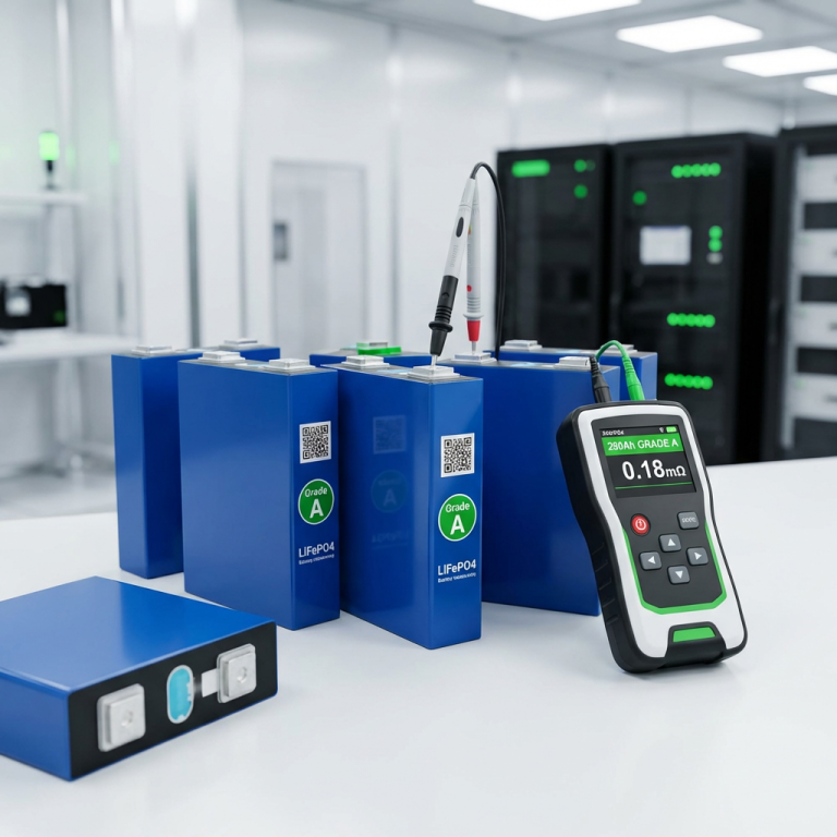
Planning a multi-stack battery installation? Contact Insum Energy today for a custom system design that prevents circulating current from day one. We supply Grade A LiFePO4 cells, JK and SEPLOS BMS systems, and complete DIY battery kits — all with CE/TUV/UN38.3 certification.
Learn more about our products at Insum Energy, or read our About Us page to see our professional capabilities.